02 UartRX
The special functino register UartRX receives bytes over UART with 8N1 at 115200 baud. When RX line goes low, the sampling process is initiated. Sampling of the individual bits is done in the middle of each bit.

Chip specification
| IN/OUT | wire | function |
|---|---|---|
| IN | clear | =1 clears the data register, chip is now ready to receive the next byte |
| IN | RX | receive wire |
| OUT | out[15] | =1 waiting for next byte, =0 byte completed |
| OUT | out[7:0] | last received byte (when out[15]=0) |
When clear = 1 the chip clears the data register and is ready to receive next byte. out[15] is set to 1 to show, that chip is ready to receive next byte. When RX goes low the chip starts sampling the RX line. After reading of byte completes, chip ouputs the received byte to out[7:0] with out[15]=0. The sampling of a complete byte takes 2170 clock cycles. Sampling is done in the middle of each bit at clock count number108.
Proposed Implementation
Use a Bit to store run state. run goes high, when rx=0 and run=0. run stops, when last bit is received. When run=1 a Counter increments every clock cycle. After 217 clock cycles the Counter resets. A second counter increments every 217 cycles to count the bits. At count number 108 the rx is shifted into a BitShift9R. When transmission of the byte completes (10-bit sampled), the content of the shiftregister is loaded into the data register with out[15] set to 0 (valid byte). The data register can be cleared by software (clear) at any time by setting the highest bit of data register to 1 (byte not ready yet).
Attention: RX must pass a DFF to be registered in the clock domain of clk.

Memory map
The special function register UartRX is mapped to memory map of HACK according to:
| address | I/O device | R/W | function |
|---|---|---|---|
| 4099 | UART_RX | R | when out[15]=1 data register is not valid, when out[15]=0 out[7:0] holds the last received byte |
| 4099 | UART_RX | W | clear data register |
echo.asm
To test HACK with UartRX we need a little machine language programm echo.asm, which reads bytes from UartRX and sends them to UART_TX.
Attention: Use a loop to wait until UartRX is ready before reading the next byte. Clear data register of UartRX after reading a byte.
Project
-
Implement
UartRX.vand simulate with test bench:$ cd 02_UartRX $ apio clean $ apio sim -
Compare with CMP:
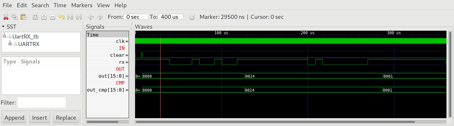
-
Edit
HACK.vand add special function registerUartRXto memory address 4099.

-
Implement
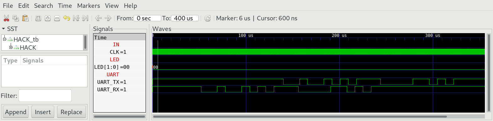
echo.asmand run in simulation:$ cd 02_UartRX $ make $ cd ../00_HACK $ apio clean $ apio sim -
Check the TX wire of the simulation and compare with the received bytes at RX.
-
build and upload HACK with
echo.asmpreloaded into ROM to iCE40HX1K-EVB. -
switch olimexino 32u4 to UART-Bridge (yellow led)
-
open terminal on your computer
-
type chars in the terminal and see if they are echoed by HACK.
$ cd 00_HACK
$ apio clean
$ apio upload
$ tio /dev/ttyACM0
